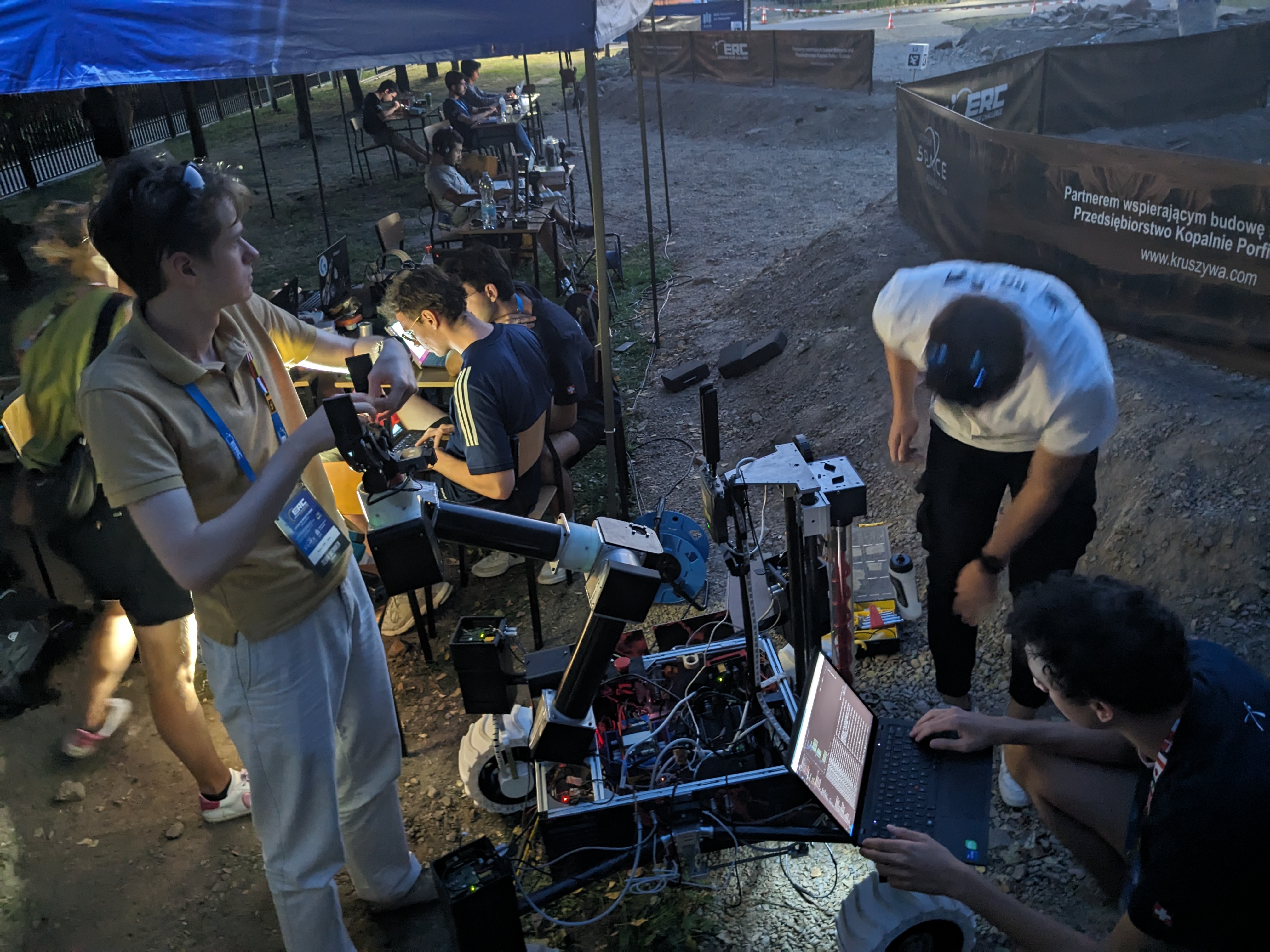
European Rover Challenge 2024
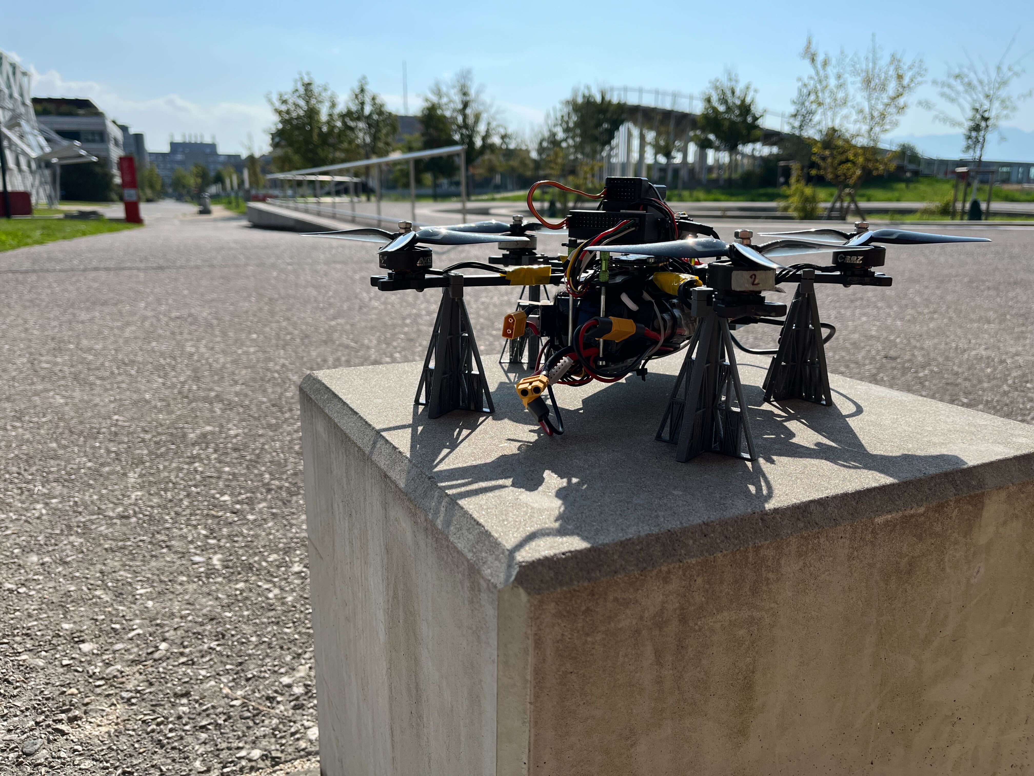
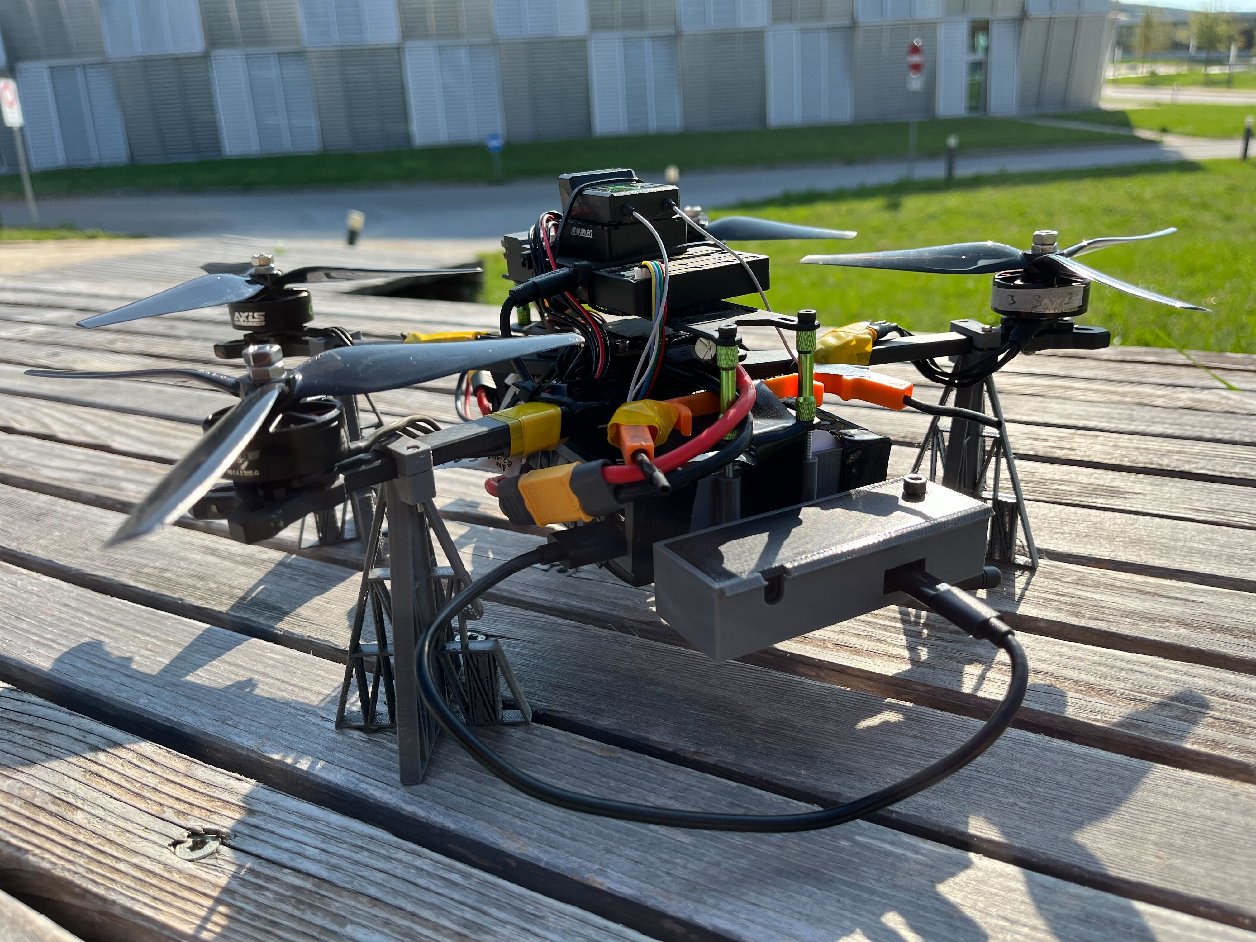
Rover & Drone Development

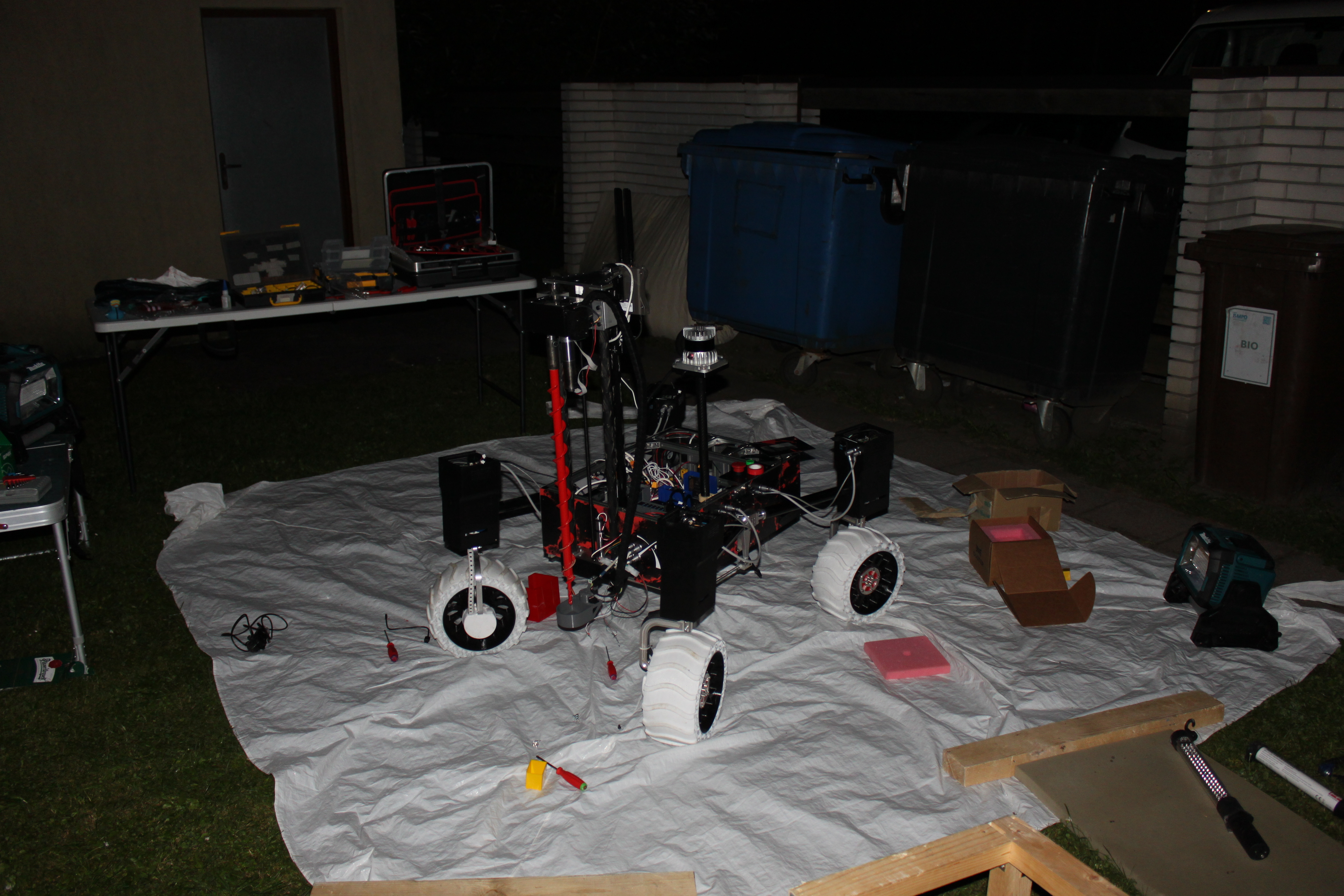
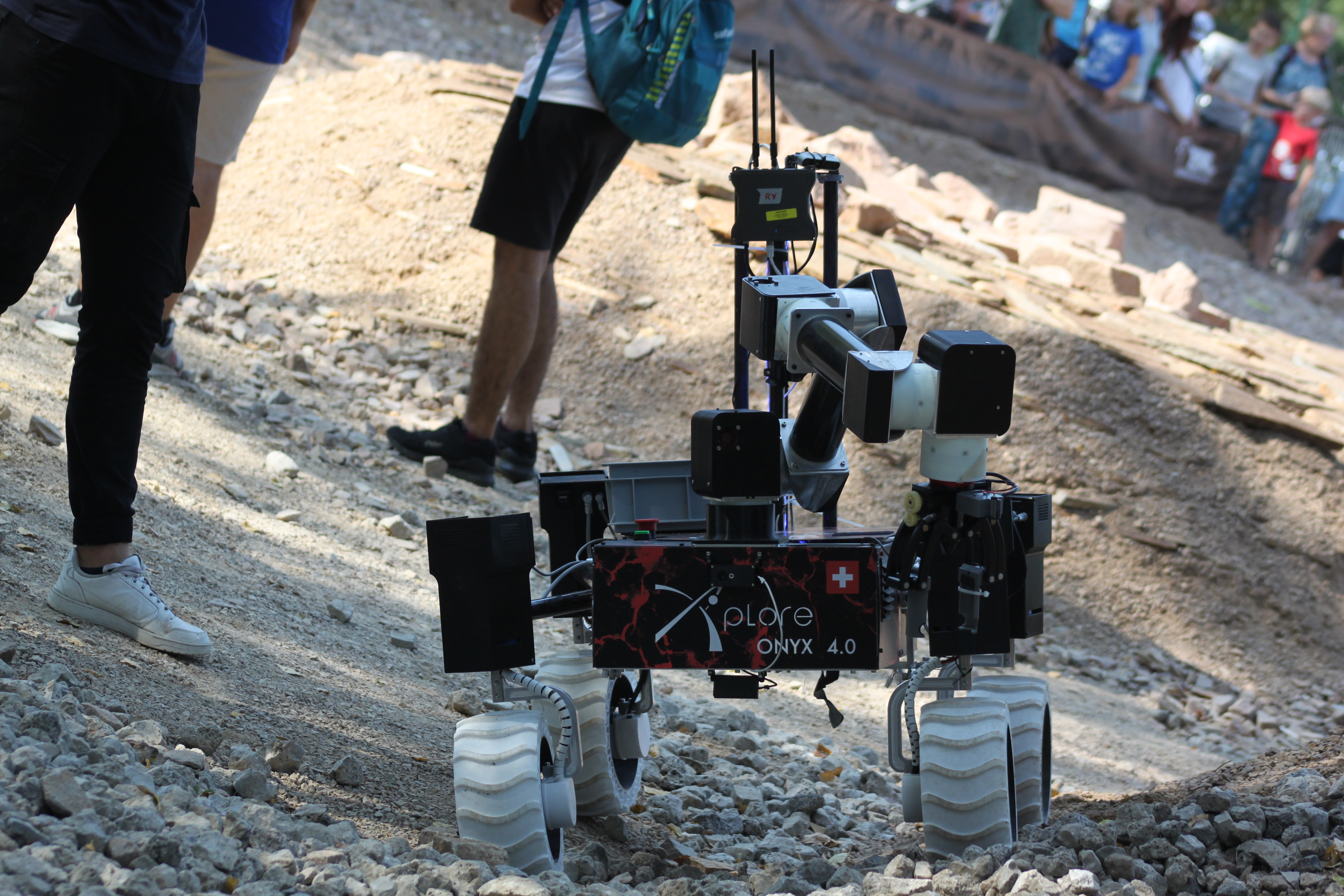
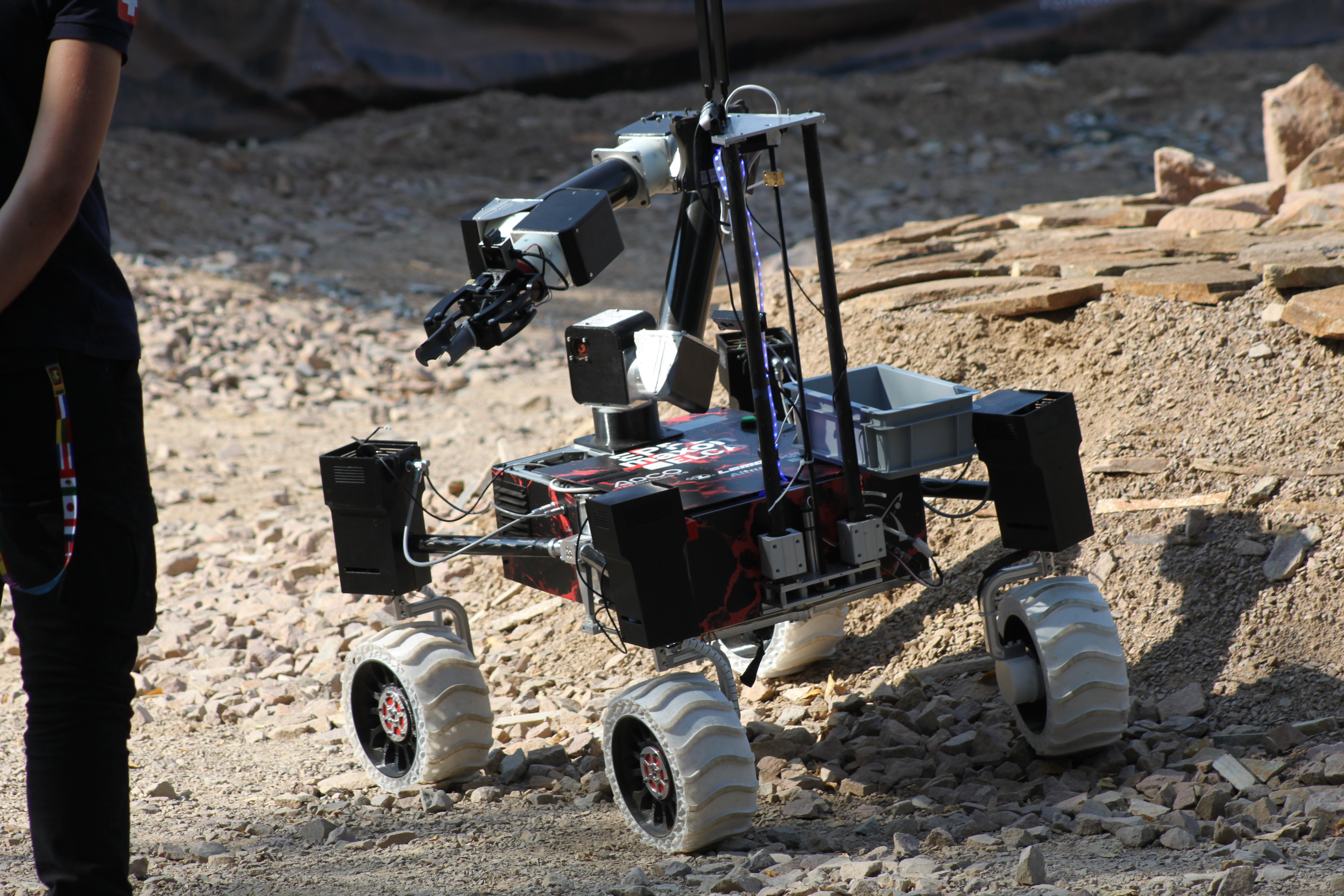
Rover Technical Overview
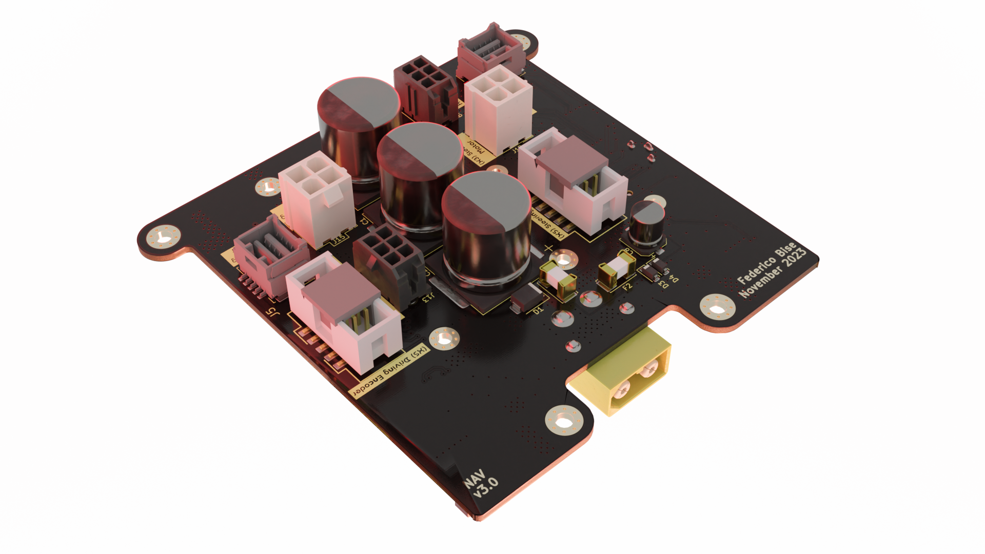
Navigation Board
To achieve a cleaner and more segmented electronic architecture, we targeted the rover's most space-consuming component: the NAV board. This critical motherboard, which hosts the MAXON motor controllers, was completely re-engineered for a radical new location, inside the rover's steerings. The new design is exceptionally compact, with custom placed ports to prevent damaging cable bends and ensure signal integrity. Now, only power and CAN bus cables run to the main chassis, while all motor actuation and sensor feedback cables are routed locally.
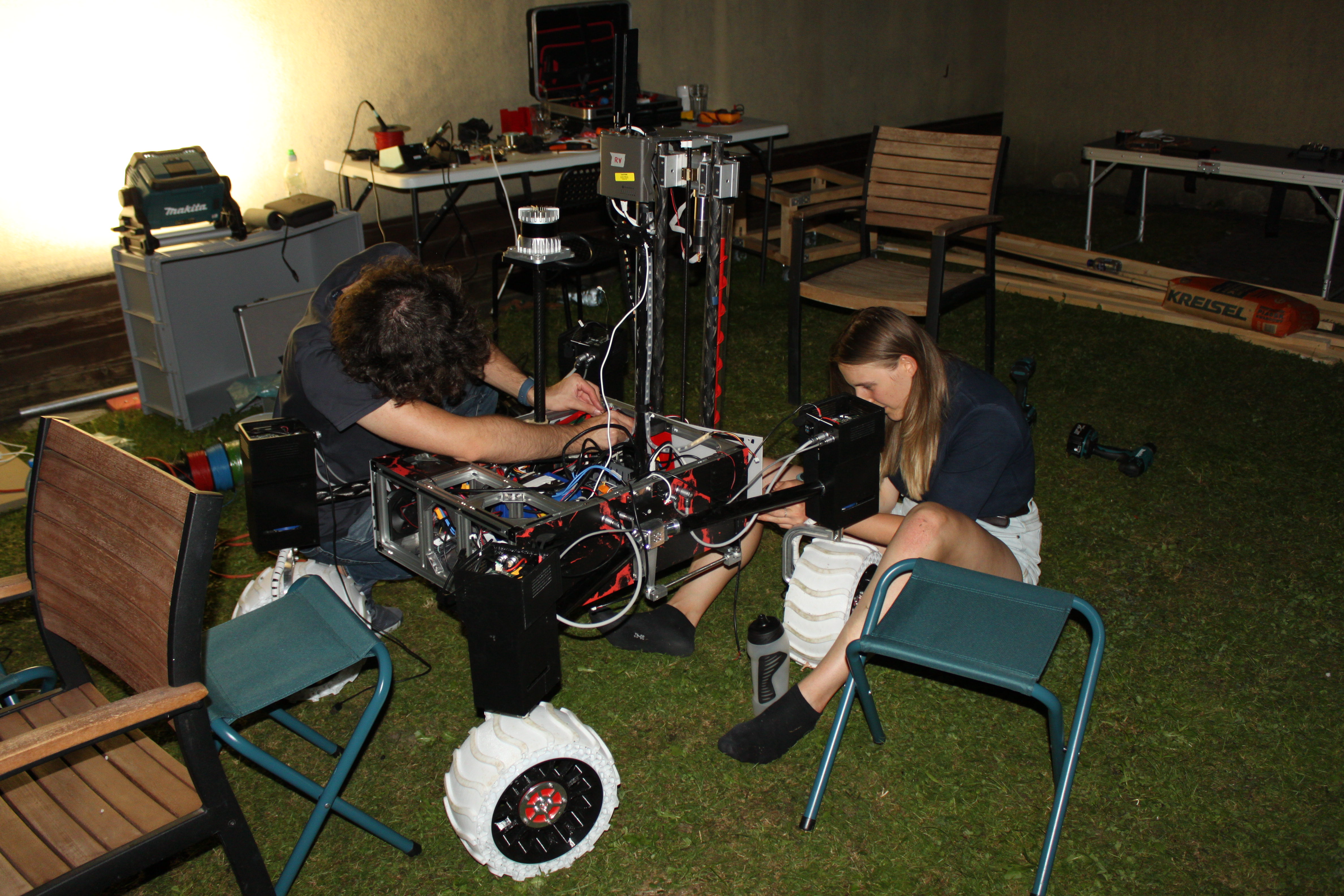
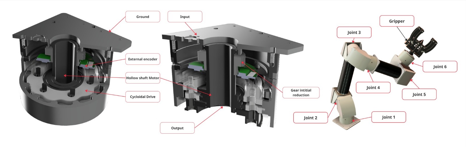
Handling device
After two years of competition, Kerby’s arm had shown clear signs of degradation, and its weaknesses became increasingly apparent. For this reason, we decided to design a new robotic arm from scratch, focusing on modularity and convenience. Our objective was to develop a universal robotic joint that could be stacked to build a 6-DoF robotic arm endowed with a custom made gripper. The mechanical requirements targeted a 5kg payload, a spherical range of one meter, the highest achievable speed under these conditions, and a hollow rotor to allow cables to pass through the entire arm. The arm was designed to weigh 10 kg. We coupled the output of Maxon motors with a complex hollow cycloidal drive, using two disks to balance potential vibrations. Together with the integrated Maxon reduction (230:1), this additional 31:1 cycloidal stage enabled us to reach uncommon torque for the joint’s size and weight. The most powerful drive at the base delivered up to 100 N·m at nominal speed after accounting for efficiency and mechanical losses. The cycloidal reduction provided low backlash and precise positioning, but since perfect motion could not be guaranteed, we implemented a controller to compensate for physical errors.
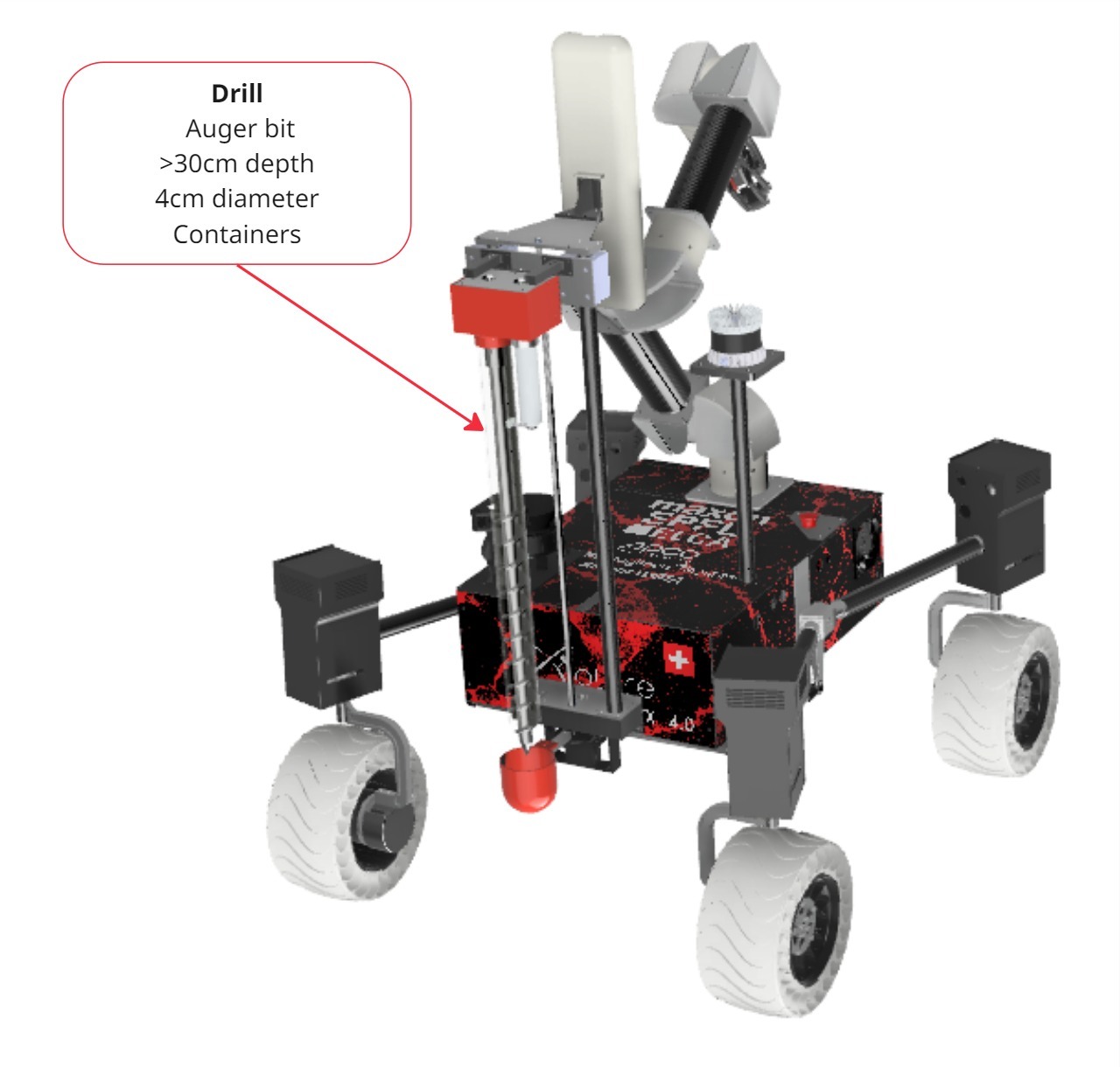
Drilling System
This year we designed a single-stage linear guiding system using a lead screw for rigidity and compactness. To limit the weight added by the screw mechanism, we used carbon tubes as linear guides. For improved stiffness, three tubes were implemented: two for guiding and one for stabilizing the structure. All remaining parts were made of aluminum to combine rigidity with lightweight properties. Compared to the previous year, we reduced the auger diameter while maintaining a similar system, with the auger rotating inside a static plexiglass tube. To measure the collected sample’s weight, we placed two load cells between the auger motor block and the linear stage. This configuration allowed the weight of the sample to be recorded and stored before release.
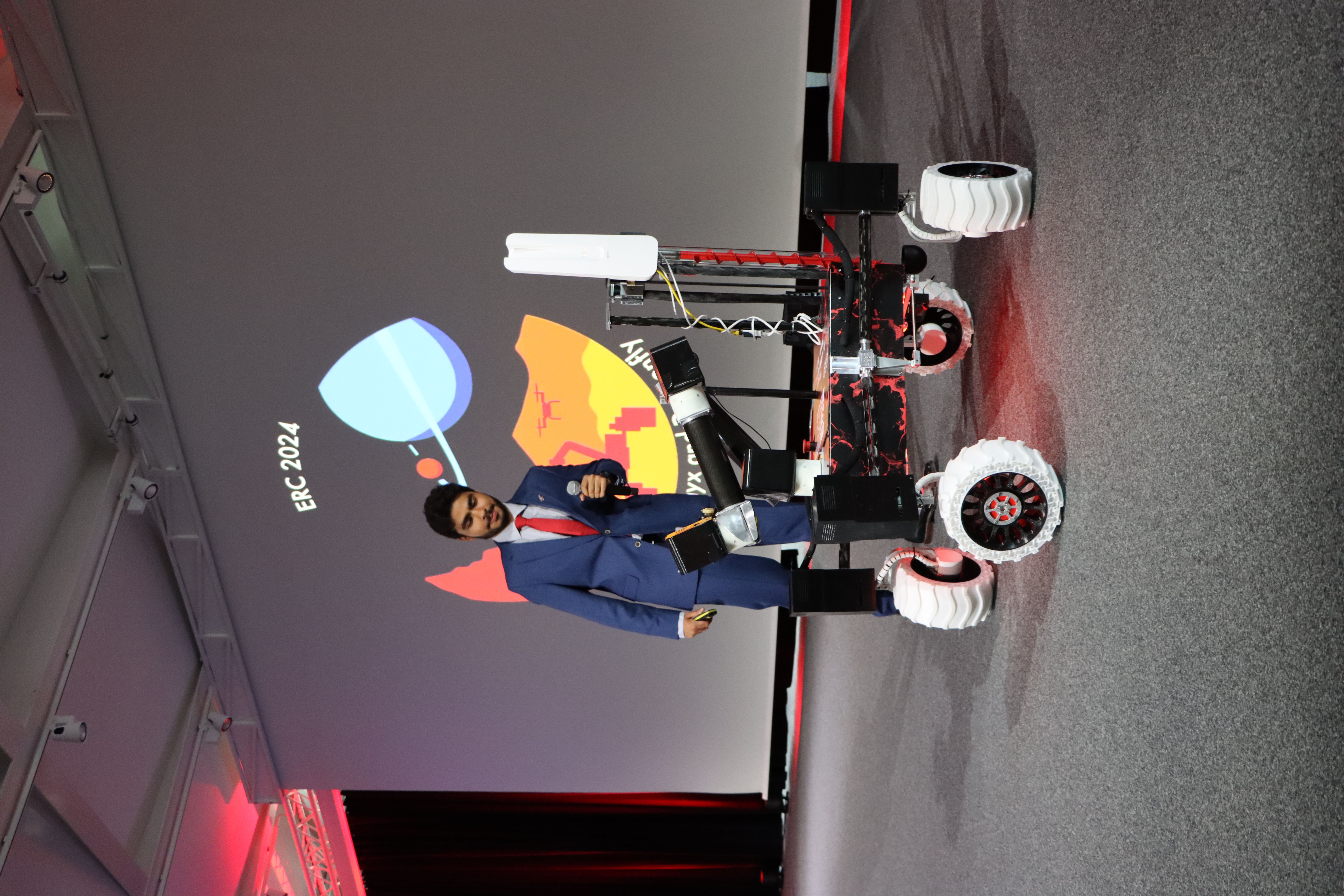
Results
13st Place Overall
Communication Issues during the competition
⭐ Presentation Excellency
Special award for the presentation of the association to the jury
Video for Qualifications
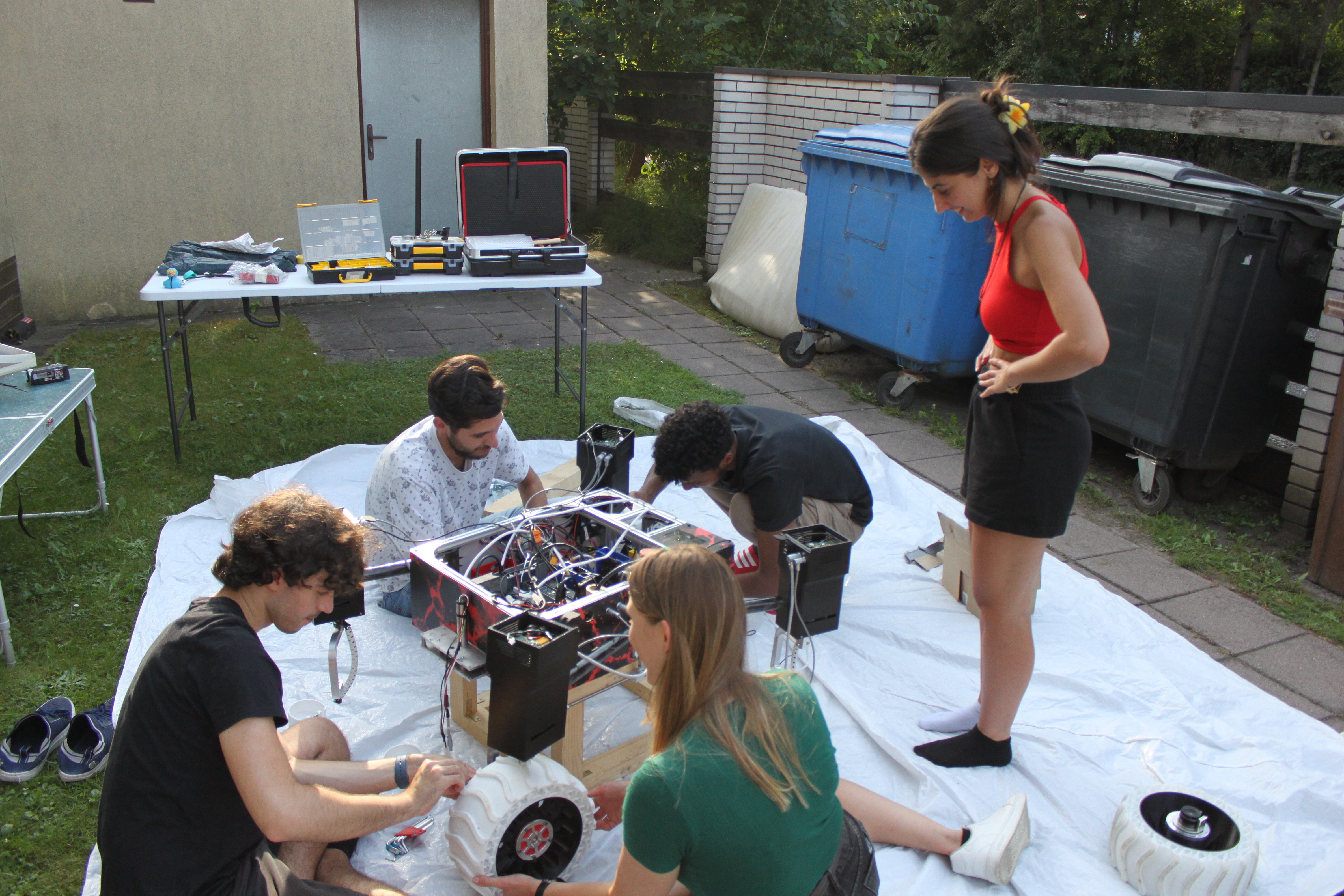
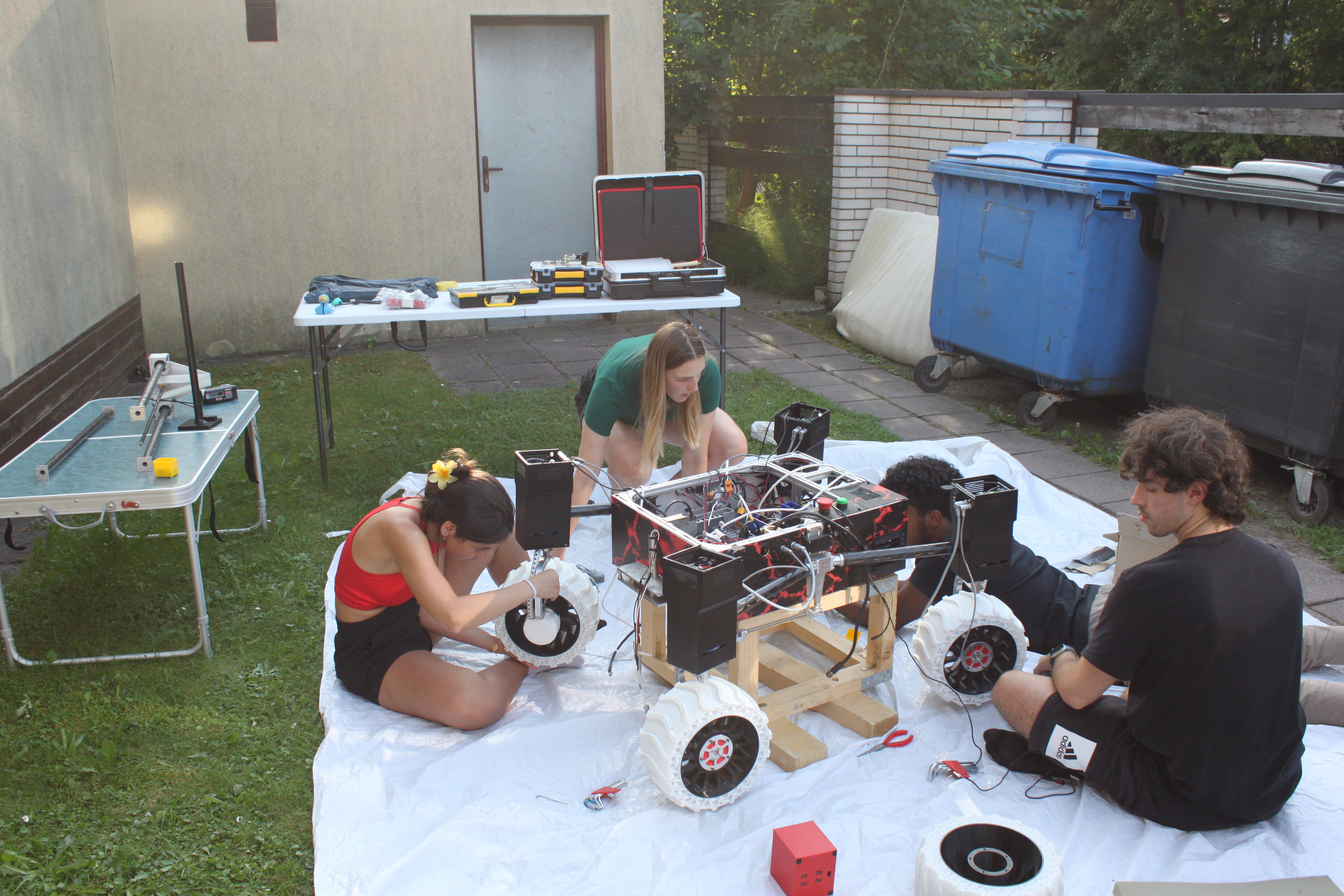
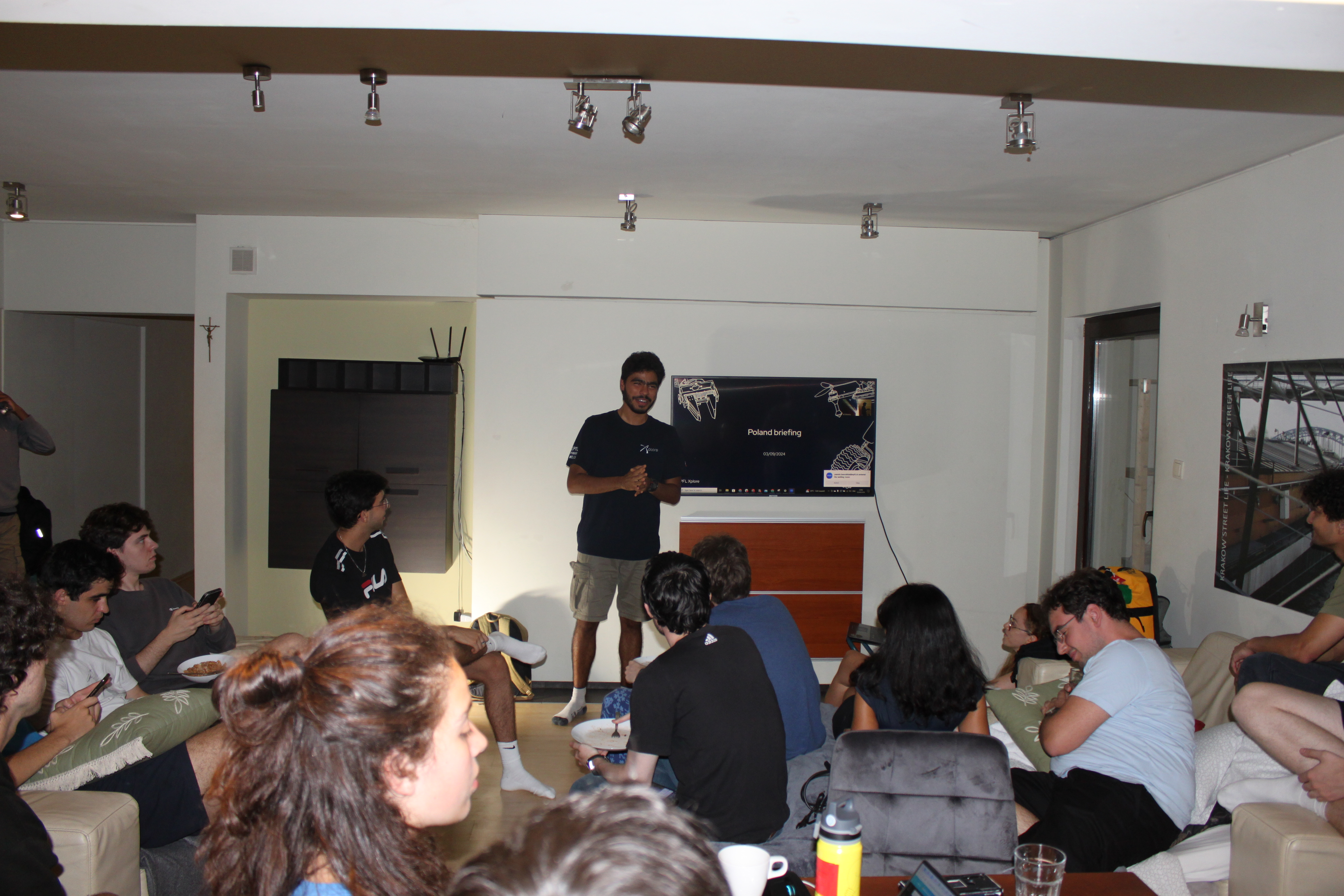
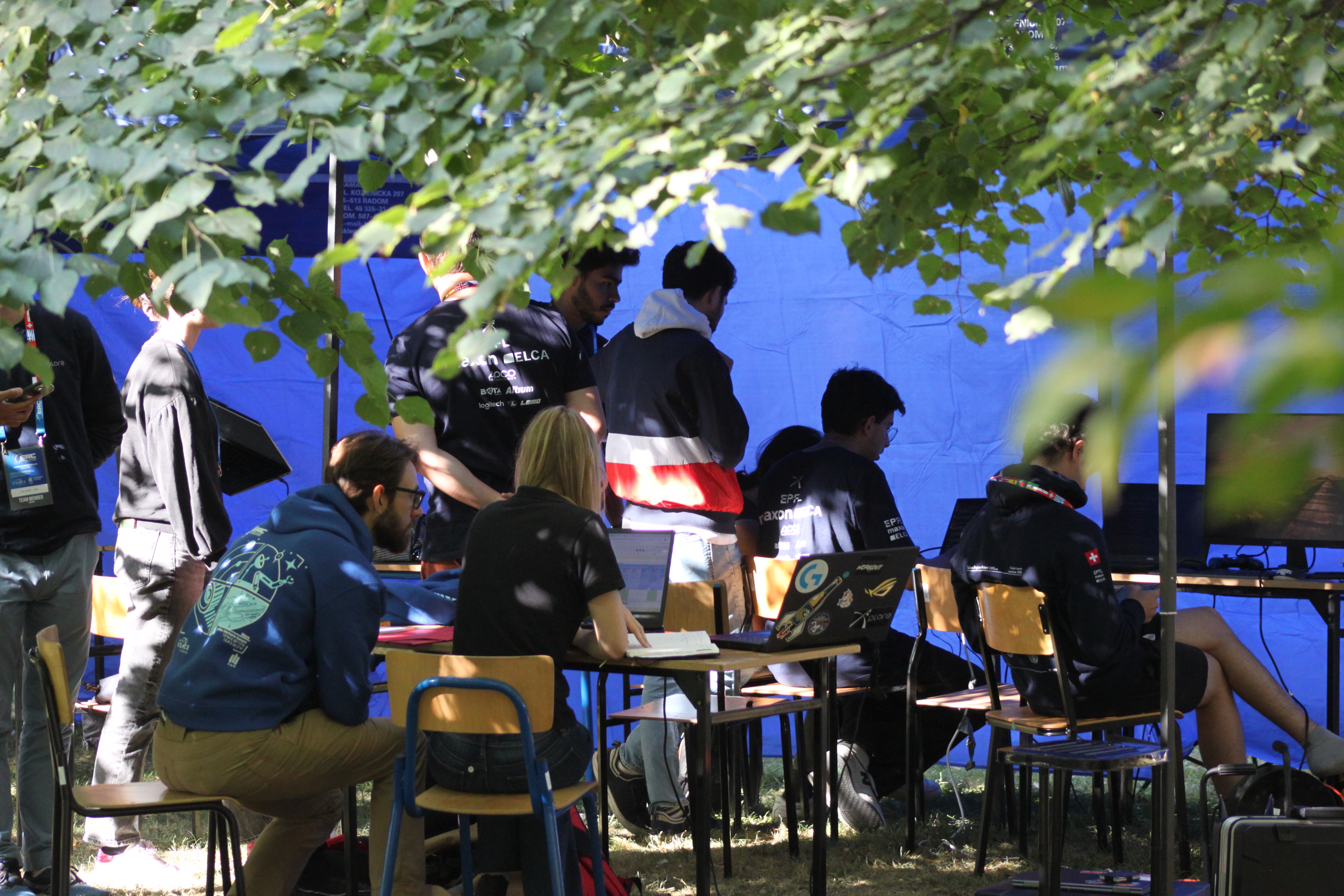
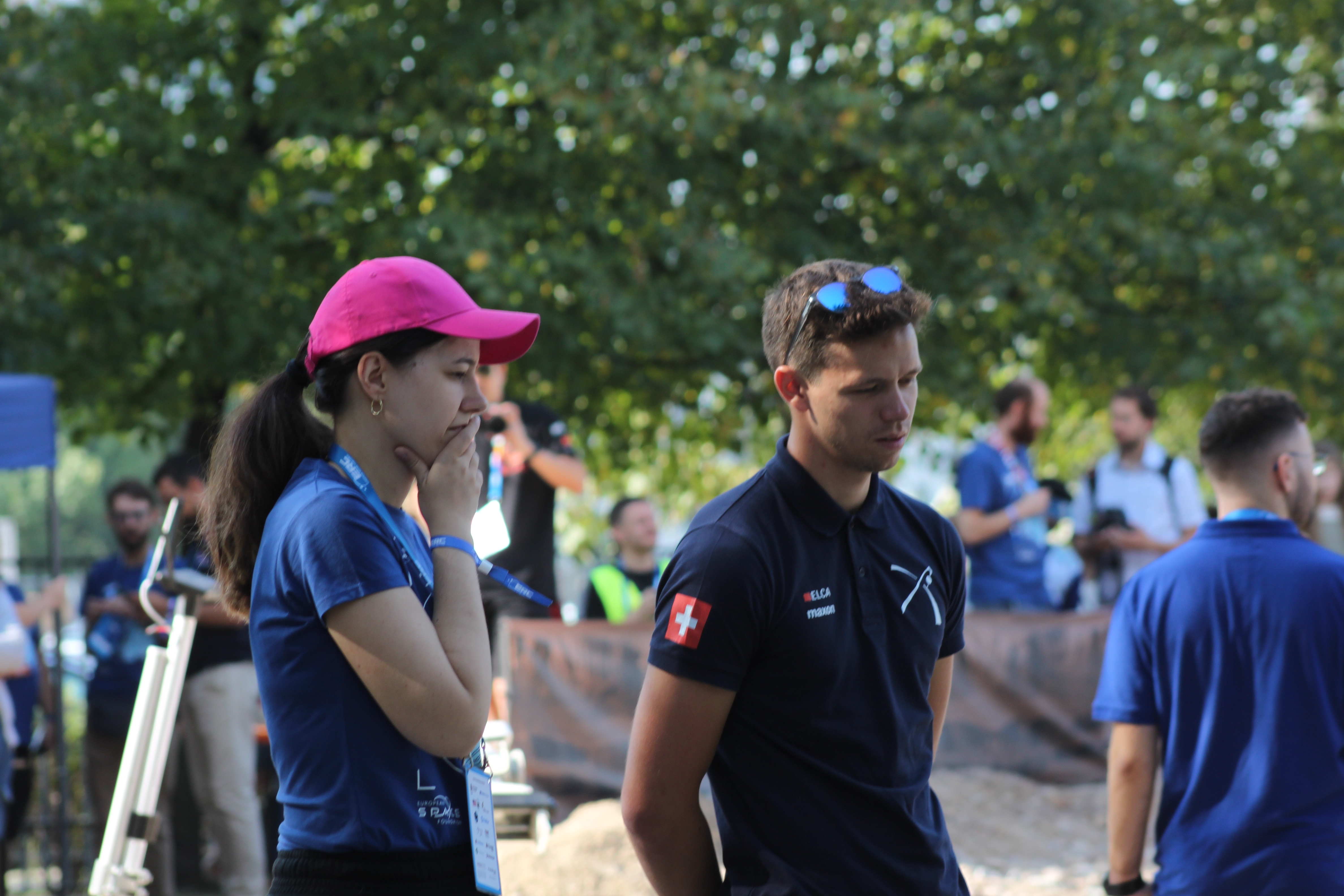
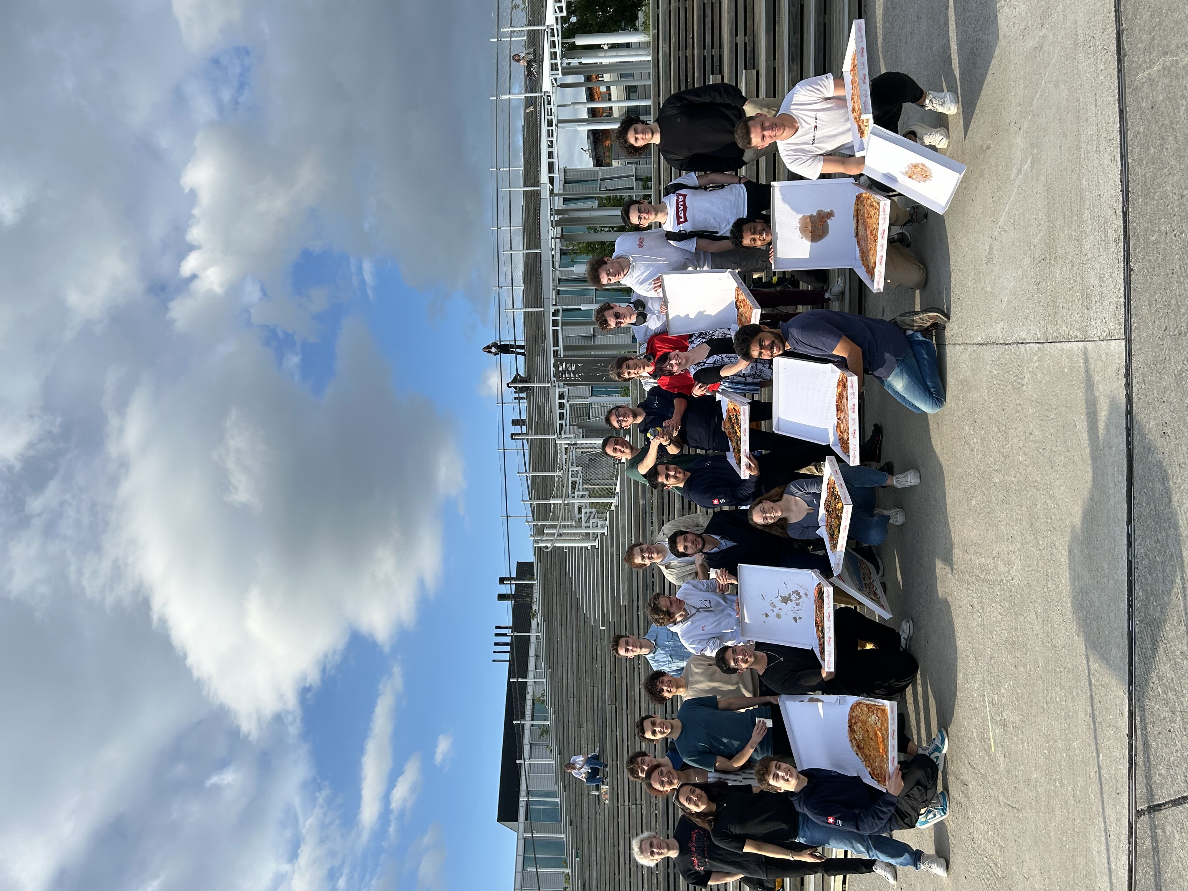
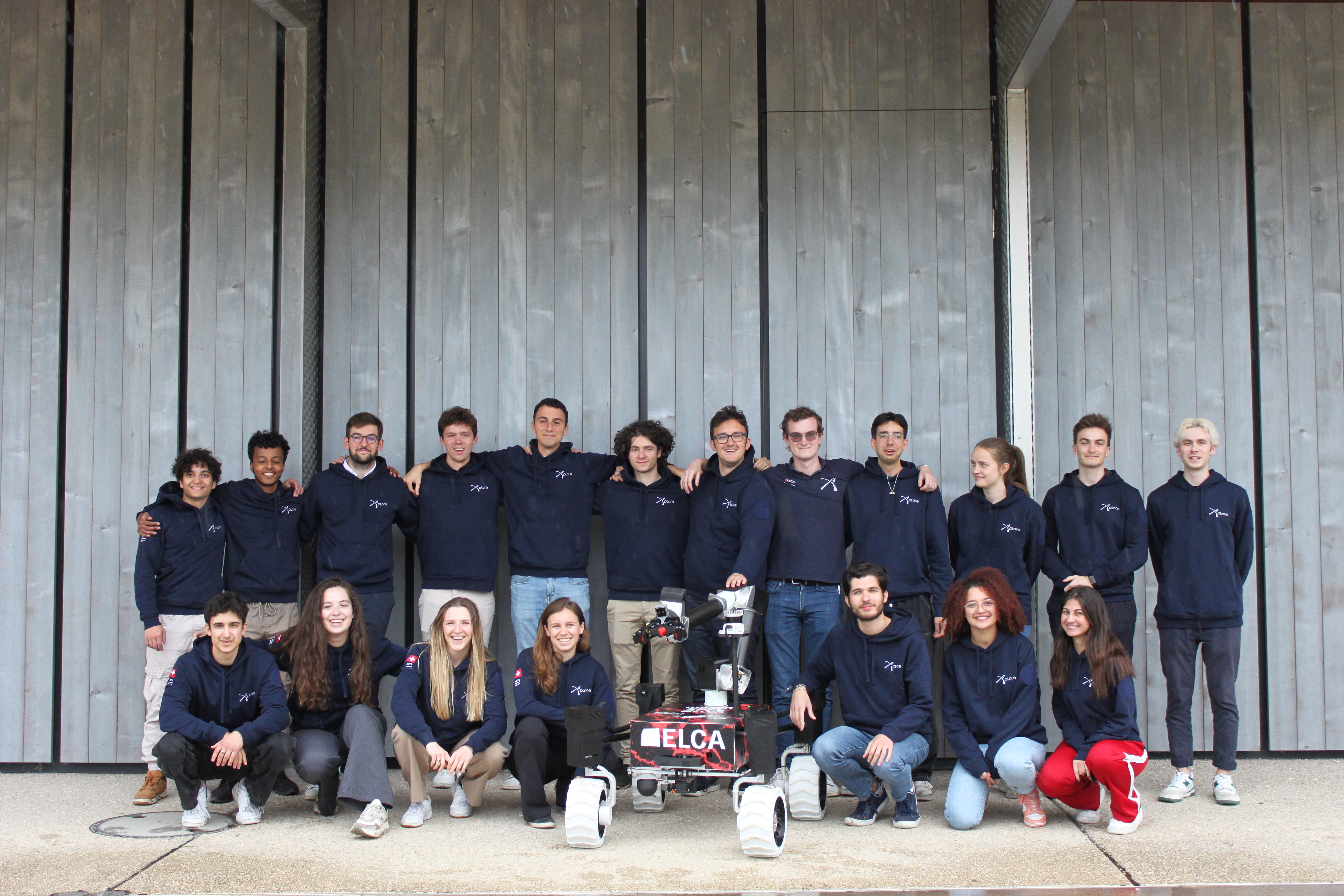
The Team

Gallery